RGB laser
So I built an RGB laser. All kinds of people on Youtube built one so how hard could it be? The possibilities of an RGB laser are endless. Who doesn’t want to play with yellow lasers? Or maybe pink mind control lasers or even a white laser just because you can?
As far as I can tell from watching other people build stuff is that all you need for an RGB laser are three laser modules sticking out at all angles, drivers for those modules and a magic crystal known as an x-cube.
The x-cube is a clever arrangement of prisms and dichroic filters that can split or combine red green and blue light. These days magic crystals can be sourced cheaply from many online marketplaces.
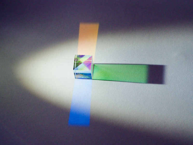
Let's design a laser assembly!
Having the lasers stick out at odd angles doesn’t seem very practical to me so let’s fold the light path with a pair of first surface mirrors so the lasers line up in a tidy row.
Much better. Now design a support structure for this in OpenSCAD and send it to a 3D printer.
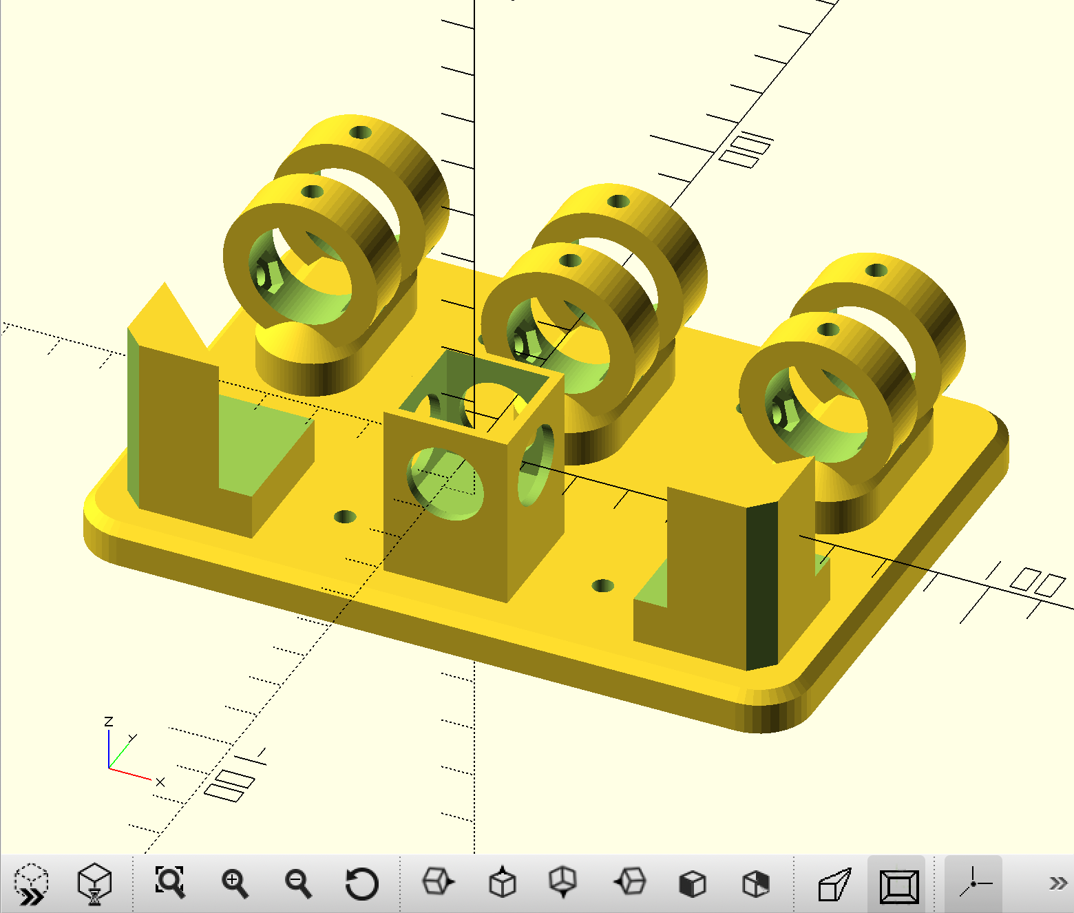
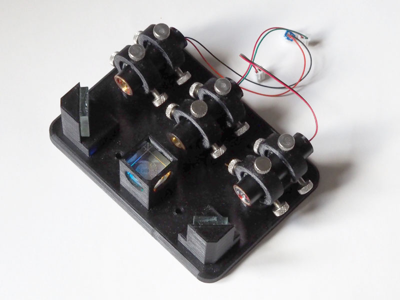
Mirrors and xcube are glued in, all 18 M4 setscrews are held in with nuts in the rings. The laser modules were glued into pieces of copper pipe with a 3D printed end cap at the back. (First law of applied optics: All optical equipment shall be made black with silver accents.)
Now the mechanical part is done we need a driver for each laser diode.
Yay, electronics!
What’s needed is an adjustable current source from around 30 to 250 mA. The exact current range differs for each laser. My DPSS green laser starts around 100mA, which is more or less the maximum current for my blue laser.
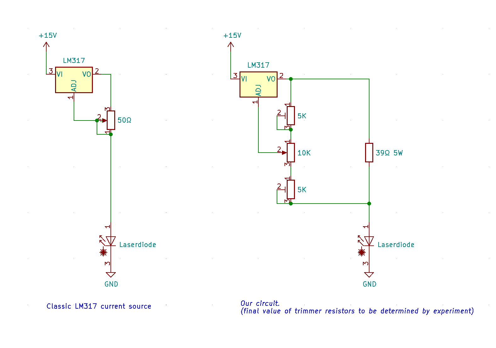
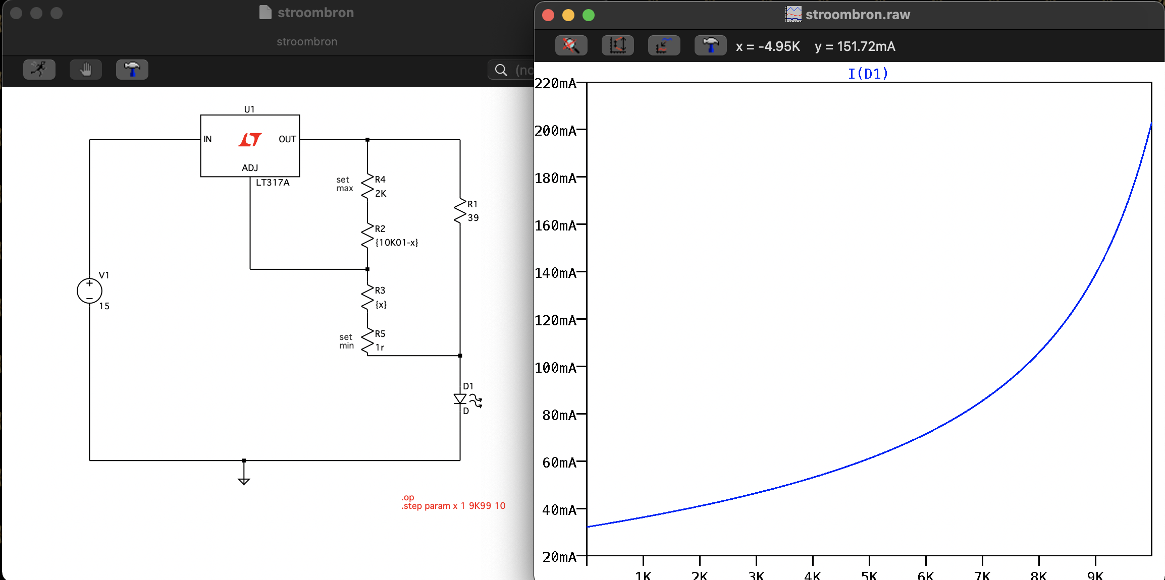
The classic LM317 current source isn’t my preferred option for this application. You’d need a beefy 50Ω potentiometer to deliver the current needed without burning up. I came up with the circuit on the right and it worked in LTspice so that’s what I’m going for.
The classic LT317 circuit maitains a constant voltage across a variable resistor to maintain a constant output current. In the modified circuit the resistor is a fixed value and the regulated voltage across it is varied.
The advantage of this circuit is that the power is dissipated in a ceramic power resistor, and we use a cheap 10K pot for adjustment. The disadvantage is that the response isn’t linear as seen in the SPICE plot below, but it’s good enough for a brightness control. The main pot is represented as R2 and R3. R4 and R5 set the range of the brightness knob. I will implement them as trimpots in the final circuit.
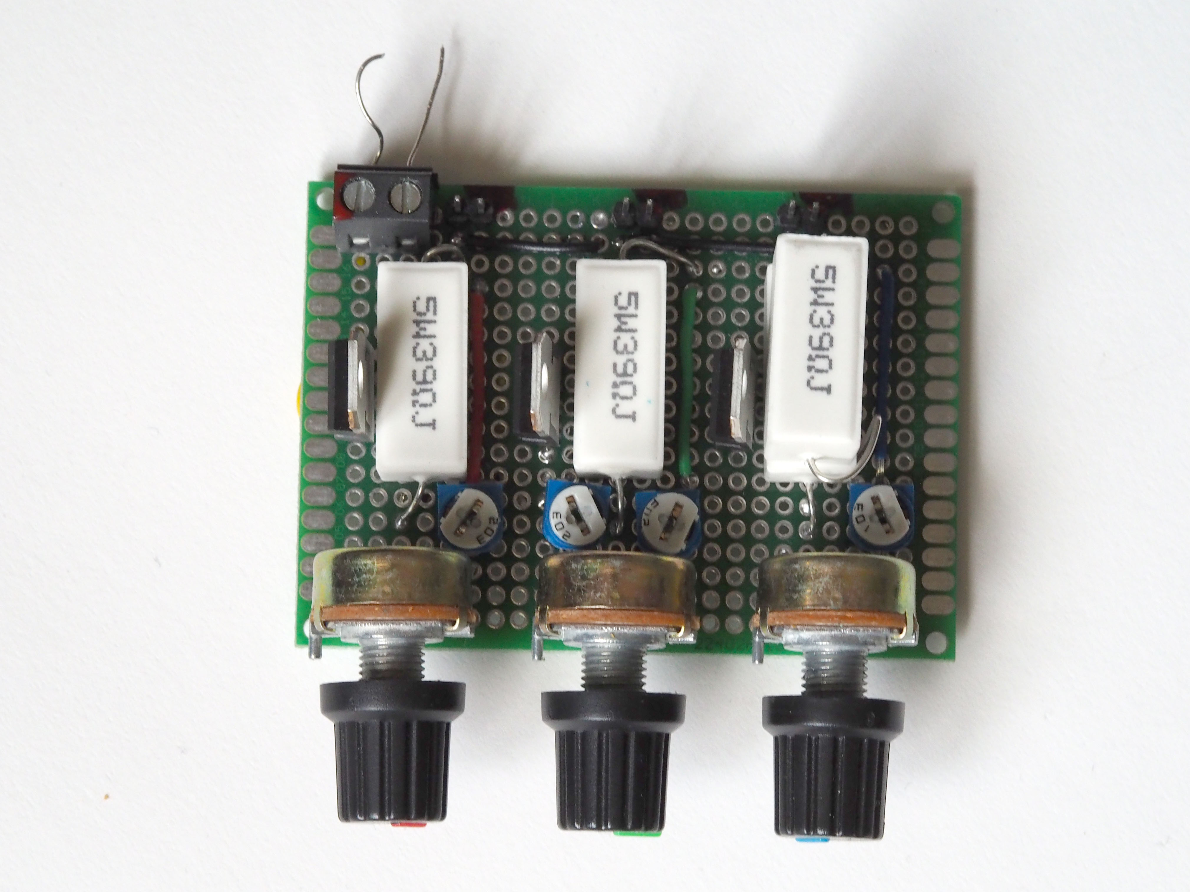
So let’s build it and fire this baby up. I’m only building one, so I’m not going to design a circuit board for this. Three of these should fit on a piece of protoboard. Only the green channel has both trimmers fitted. Red and blue only have a single trimmer to set the maximum current. The blue channel uses two 39Ω in series to produce a lower current range.
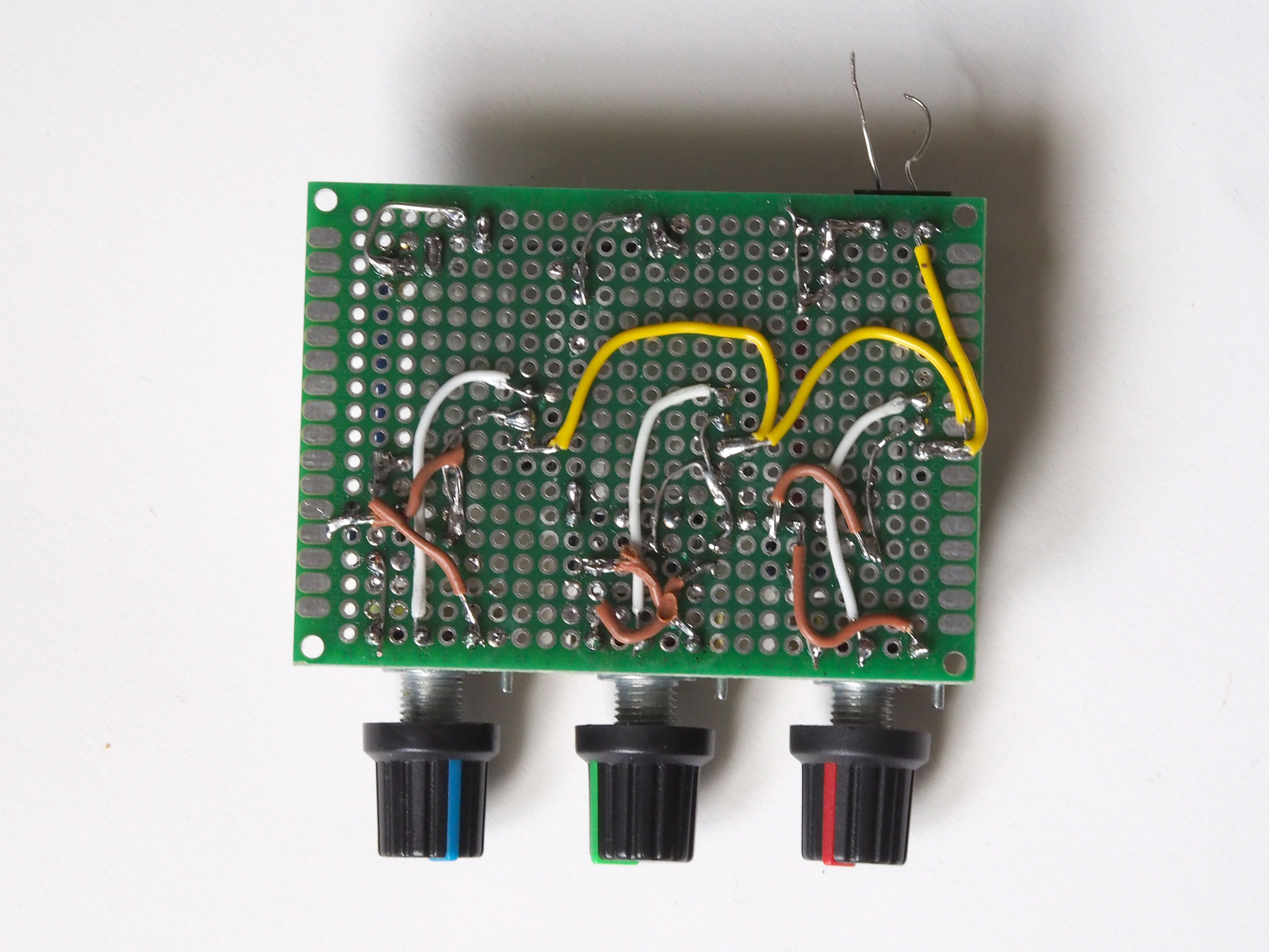
Neat protoboard soldering is a great skill to have. Sadly it’s a skill I do not posess.
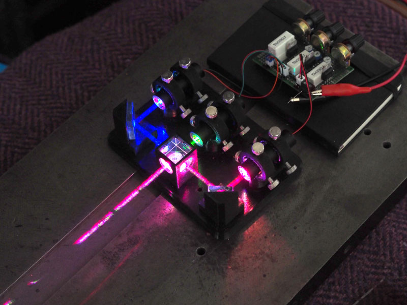
Finally results!
Lining up the lasers by adjusting 18 screws is a bit fiddly, but once everything is aligned things look pretty good. I may have sprayed something in the air to make the beams visible. the red beam looks a lot brighter on camera than to the naked eye.
Tuning the laser through the rim of the color wheel.
And a perfectly innocent shot of my new laser being put to good use.
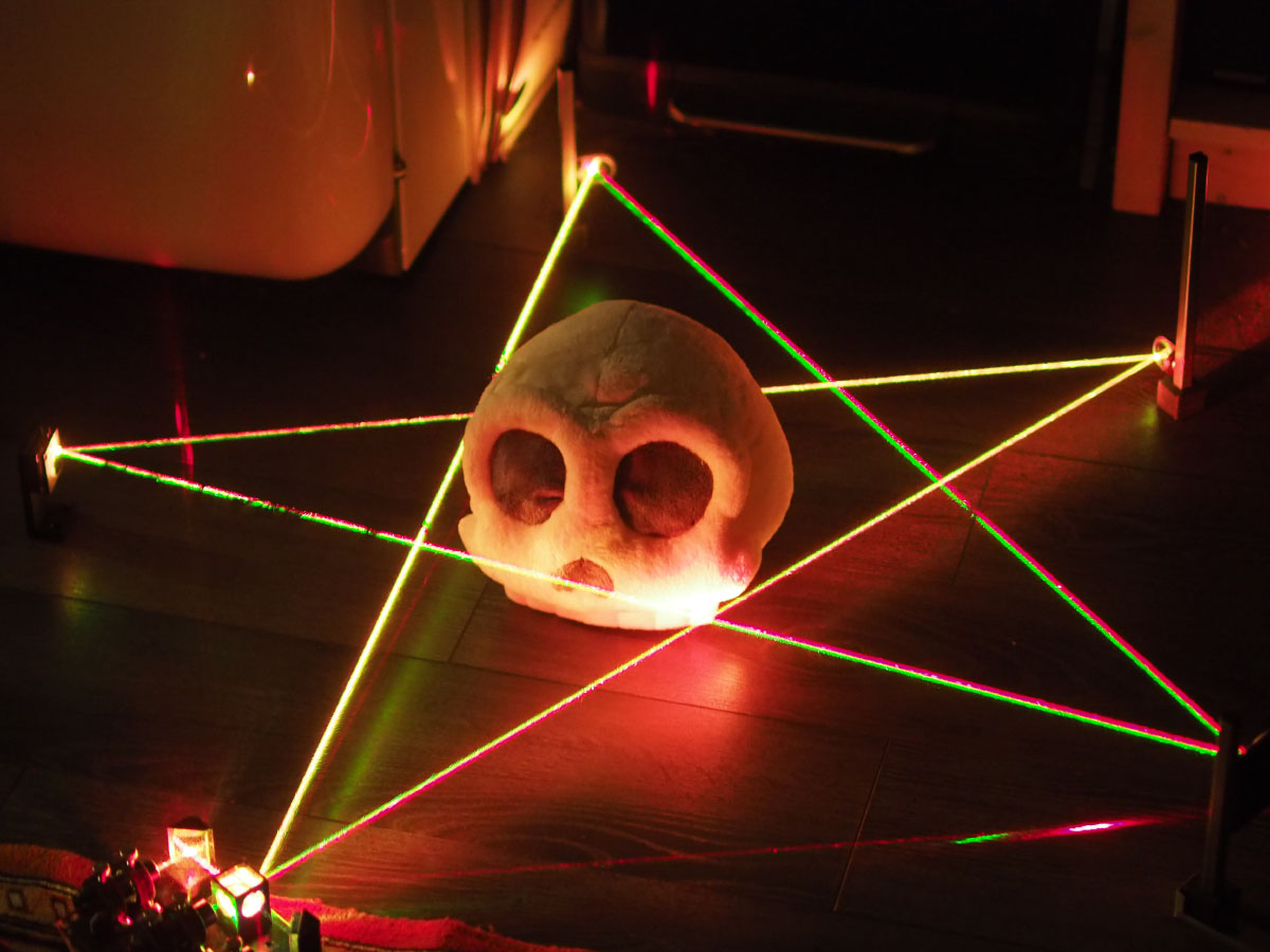
No plushies were harmed in the making of this post.
